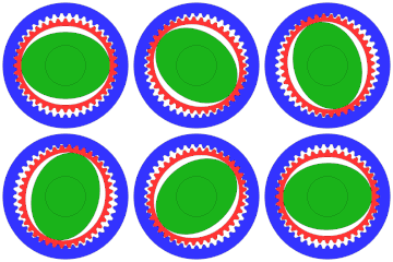
function HarmonicDriveAni()
% source code for drawing a HarmonicDrive
% this is by no means a "simulation". It is a hack job that produces a gif
%
% 2016-12-05 Jahobr (reworked 2017-09-16)


nTeethOutGear =  42;
nTeethFlex = nTeethOutGear-2;
modul = 0.1; % modul

colEdge = [0   0   0  ]; % Edge color
colFlex = [1   0.2 0.2]; % FlexSpline color
colWave = [0.1 0.7 0.1]; % WaveGen color
colGear = [0.2 0.2 1  ]; % static OuterGear color

nFrames = 100;
frameAngles = linspace(0,-pi,nFrames+1); % rotate clockwise
frameAngles = frameAngles(1:end-1); % delete redundant frame

[pathstr,fname] = fileparts(which(mfilename)); % save files under the same name and at file location

figHandle = figure(15674454);
clf
axesHandle = axes;
hold(axesHandle,'on')
axis equal
xlim([-3 3])
ylim([-3 3])
set(figHandle, 'Units','pixel');
set(figHandle, 'position',[1 1 700 700]); % [x y width height]
set(axesHandle, 'position',[-0.05 -0.05 1.1 1.1]); % stretch axis bigger as figure, easy way to get rid of ticks [x y width height]
set(figHandle,'GraphicsSmoothing','on') % requires at least version 2014b

for iFrame = 1:nFrames

    angleWaveGen = frameAngles(iFrame);
    angleFlexTeeth = angleWaveGen*(nTeethFlex-nTeethOutGear)/nTeethFlex; %  angle of the flexspline

    cla(axesHandle);

    %% %%%%%%%%    draw OuterGear (static)   %%%%%%%%
    %% %%%%%%%%%%%%%%%%%%%%%%%%%%%%%%%%%%%%%%%%%%%%%%

    effectiveDiameter = modul*nTeethOutGear;
    toothTipDiameter = effectiveDiameter-1.4*modul;
    toothBottomDiameter = effectiveDiameter+1.6*modul;

    angleBetweenTeeth = 2*pi/nTeethOutGear; % angle between 2 teeth
    angleOffPoints = (0:angleBetweenTeeth/8:(2*pi));

    %% outerEdge
    maxDiameter = toothBottomDiameter*1.2; % definition of outer line
    maxXY = samplesEllipse(maxDiameter,maxDiameter,500);
    patch(maxXY(:,1),maxXY(:,2),colGear,'EdgeColor',colEdge,'LineWidth',0.5) % full outer disc

    %% inner teeth
    radiusOffPoints = angleOffPoints; % init

    radiusOffPoints(1:8:end) = toothBottomDiameter/2; % middle bottom
    radiusOffPoints(2:8:end) = toothBottomDiameter/2; % left bottom
    radiusOffPoints(3:8:end) = effectiveDiameter/2; % rising edge
    radiusOffPoints(4:8:end) = toothTipDiameter/2; % right top
    radiusOffPoints(5:8:end) = toothTipDiameter/2; % middle top
    radiusOffPoints(6:8:end) = toothTipDiameter/2; % left top
    radiusOffPoints(7:8:end) = effectiveDiameter/2; % falling edge
    radiusOffPoints(8:8:end) = toothBottomDiameter/2; % right bottom

    [X,Y] = pol2cart(angleOffPoints,radiusOffPoints);

    patch(X,Y,[1 1 1],'EdgeColor',colEdge,'LineWidth',0.5) % overlay white area for inner teeth


    %% %%%%%%%%%     draw Flexspline        %%%%%%%%%
    %% %%%%%%%%%%%%%%%%%%%%%%%%%%%%%%%%%%%%%%%%%%%%%%

    % % deform estimation based on tooth distance (using the circumferences); could be automated!
    % U1 = 42*pi % Circumference of OuterGear
    % U1 =
    %   131.9469
    %
    % U2 = pi*sqrt(2*((42/2)^2+(0.9022*42/2)^2))  * 42/40 % Circumference of Flexspline * 42/40
    % U2 =
    %   131.9435
    deform = 0.9022;

    deformedDiameter = effectiveDiameter*deform; % scale down, but teeth must still have the same distance

    rootEffectiveDia = effectiveDiameter-1.6*modul; % fixed offset
    rootDeformedDia  = deformedDiameter-1.6*modul;  % fixed offset

    topEffectiveDia = effectiveDiameter+1.4*modul; % fixed offset
    topDeformedDia  = deformedDiameter+1.4*modul;  % fixed offset

    % % an equidistant sampled ellipse is needed, to keep the tooth distance constant all the way around
    offsetOnCircumference = (-angleWaveGen+angleFlexTeeth)/2/pi; % compensation + own_rotation  ,  normalization to "circumference"
    equiEffeXY = equidistantSamplesEllipse(effectiveDiameter,deformedDiameter,nTeethFlex*8, offsetOnCircumference); % points on effective diameter
    equiRootXY = equidistantSamplesEllipse(rootEffectiveDia, rootDeformedDia, nTeethFlex*8, offsetOnCircumference); % points with inwards offset
    equiOutXY  = equidistantSamplesEllipse(topEffectiveDia,  topDeformedDia,  nTeethFlex*8, offsetOnCircumference); % points with outwards offset

    toothXY = equiEffeXY; % intit

    toothXY(1:8:end,:) = equiOutXY(1:8:end,:); % middle top        I######I
    toothXY(2:8:end,:) = equiOutXY(2:8:end,:); % left top          I######+
    % toothXY(3:8:end) init did it                                 I####/
    toothXY(4:8:end,:) = equiRootXY(4:8:end,:); % right bottom     I##+
    toothXY(5:8:end,:) = equiRootXY(5:8:end,:); % middle bottom    I##I
    toothXY(6:8:end,:) = equiRootXY(6:8:end,:); % left bottom      I##+
    % toothXY(7:8:end) init did it                                 I####\
    toothXY(8:8:end,:) = equiOutXY(8:8:end,:); % right top         I######+

    [toothXY] = rotateCordiantes(toothXY,angleWaveGen);

    patch(toothXY(:,1),toothXY(:,2),colFlex,'EdgeColor',colEdge,'LineWidth',0.5) %draw flexspline with teeth


    %% hole
    holeEffectiveDia = effectiveDiameter-5*modul; % fixed inwards offset
    holeDeformedDia  = deformedDiameter-5*modul;  % fixed inwards offset

    holePathXY = samplesEllipse(holeEffectiveDia,holeDeformedDia,500);
    holePathXY = rotateCordiantes(holePathXY,angleWaveGen);
    patch(holePathXY(:,1),holePathXY(:,2),[1 1 1],'EdgeColor',colEdge,'LineWidth',0.5) % draw hole of deformed ring


    %% %%%%%%%%%   draw wave generator      %%%%%%%%%
    %% %%%%%%%%%%%%%%%%%%%%%%%%%%%%%%%%%%%%%%%%%%%%%%

    waveEffectiveDia = holeEffectiveDia; % touch flex spline
    waveDeformedDia  = holeDeformedDia-5*modul; % extra air gap to spline, to make it more obvious

    wavePathXY = samplesEllipse(waveEffectiveDia,waveDeformedDia,500);
    [wavePathXY] = rotateCordiantes(wavePathXY,angleWaveGen);
    patch(wavePathXY(:,1),wavePathXY(:,2),colWave,'EdgeColor',colEdge,'LineWidth',0.5) % draw wave generator

    %% central shaft
    shaftPathXY = samplesEllipse(effectiveDiameter/2.5,effectiveDiameter/2.5,500);
    plot(axesHandle,shaftPathXY(:,1),shaftPathXY(:,2),'LineWidth',0.8,'color',colEdge); % draw central shaft outline


    %% %%%%%%%%%   save animation     %%%%%%%%%
    %% %%%%%%%%%%%%%%%%%%%%%%%%%%%%%%%%%%%%%%%%%%%%%%

    drawnow;

    f = getframe(figHandle);
    if iFrame == 1 % create colormap
        [im,map] = rgb2ind(f.cdata,32,'nodither'); % 32 colors % create color map %% THE FIRST FRAME MUST INCLUDE ALL COLORES !!!
        % FIX WHITE, rgb2ind sets white to [0.9961    0.9961    0.9961], which is annoying
        [~,wIndex] = max(sum(map,2)); % find "white"
        map(wIndex,:) = 1; % make it truly white
        im(1,1,1,nFrames) = 0; % allocate

        if ~isempty(which('plot2svg'))
            plot2svg(fullfile(pathstr, [fname '_Frame1.svg']),figHandle) % by Juerg Schwizer
        else
            disp('plot2svg.m not available; see http://www.zhinst.com/blogs/schwizer/');
        end
    end

    imtemp = rgb2ind(f.cdata,map,'nodither');
    im(:,:,1,iFrame) = imtemp;

end
imwrite(im,map,fullfile(pathstr, [fname '.gif']),'DelayTime',1/30,'LoopCount',inf) % save gif
disp([fname '.gif  has ' num2str(numel(im)/10^6 ,4) ' Megapixels']) % Category:Animated GIF files exceeding the 50 MP limit

%%% equidistantSamplesEllipse test code
% figure(455467);clf;hold on;
%
% equidistantXY = equidistantSamplesEllipse(1.5,0.5,40,0.1);
% plot(equidistantXY(:,1),equidistantXY(:,2),'bx-')
%
%
% equidistantXY = equidistantSamplesEllipse(2,1,40,1);
% plot(equidistantXY(:,1),equidistantXY(:,2),'bx-')
%
% equidistantXY = equidistantSamplesEllipse(3,2,40,0.5);
% plot(equidistantXY(:,1),equidistantXY(:,2),'bx-')
%
% equidistantXY = equidistantSamplesEllipse(4,3,40,0);
% plot(equidistantXY(:,1),equidistantXY(:,2),'bx-')
% pathXY = samplesEllipse(4,3,41);
% plot(pathXY(1:end-1,1),pathXY(1:end-1,2),'ro-')
%
% plot([4 -4]/2,[0 0],'-k')


function equidistantXY = equidistantSamplesEllipse(diameterH,diameterV,nPoints,offset)
% Inputs:
%   diameterH  horizontal diameter
%   diameterV  vertical diameter
%   nPoints    number of resampled points
%   offsetFraction between 0 and 1 in circumference of ellipse

pathXY = samplesEllipse(diameterH,diameterV,1000); % create ellipse
stepLengths = sqrt(sum(diff(pathXY,[],1).^2,2)); % distance between the points
stepLengths = [0; stepLengths]; % add the starting point
cumulativeLen = cumsum(stepLengths); % cumulative sum
circumference = cumulativeLen(end);
finalStepLocs = linspace(0,1, nPoints+1)+offset; % equidistant distribution
finalStepLocs = finalStepLocs(1:end-1); % remove redundant point
finalStepLocs = mod(finalStepLocs,1)*circumference; % unwrap and scale to circumference
equidistantXY = interp1(cumulativeLen, pathXY, finalStepLocs);


function pathXY = samplesEllipse(diameterH,diameterV,nPoints)
% point of ellipse; points start on the right, counterclockwise
% first and last points are the same
%
% Inputs:
%   diameterH  horizontal diameter
%   diameterV  vertical diameter
%   nPoints    number of points

p = linspace(0,2*pi,nPoints)';
pathXY = [cos(p)*diameterH/2 sin(p)*diameterV/2]; % create ellipse


function [xy] = rotateCordiantes(xy,anglee)
% [x1 y1; x2 y2; x3 y3; ...] coordinates to rotate
% anglee angle of rotation in [rad]
rotM = [cos(anglee) -sin(anglee); sin(anglee) cos(anglee)];
xy = (rotM*xy')';


