Fichier:Superheterodyne image problem.svg

Ce fichier et sa description proviennent de Wikimedia Commons.
Description
| Description |
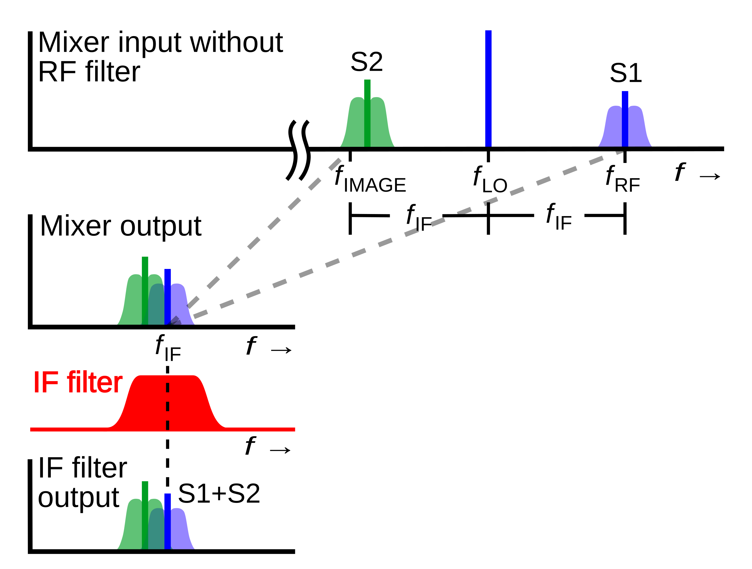
English: Diagram of the radio signals at different points in a superheterodyne radio receiver showing the problem of image response and why the receiver needs an RF image filter on the input. The horizontal axis is frequency while the vertical axis is voltage. The diagrams show what would happen in a superheterodyne without an RF filter.
In the superheterodyne the signal of the desired radio station (S1, blue) at frequency is mixed with a sinusoidal signal from a local oscillator (LO) at frequency , producing a heterodyne or "beat" frequency at the difference between the two frequencies, called the intermediate frequency (IF) at . After being shifted to the intermediate frequency, the signal S1 passes through the IF filter which removes signals at all other frequencies, and is demodulated. However there is a second frequency on the other side of the LO frequency which also produces a heterodyne at the IF frequency when mixed with the LO. This is called the image frequency . Thus the superheterodyne receives on two frequencies: Русский: Графики радиосигналов в разных точках супергетеродинного радиоприемника иллюстрирующие возникновение и прохождение по тракту помехи с зеркальной частотой и поясняющая почему приемнику обычно необходим входной радиочастотный фильтр. По горизонтальной осотложена частота сигналов, а вертикальная ось — напряжение, или на красном графике коэффициент передачи фильтра в зависимости от частоты. На диаграммах показано влияние помехи по зеркальному каналу в супергетеродине без входного фильтра. В супергетеродине сигнал нужной радиостанции (S1, синий) на частоте смешанный с синусоидальным сигналом от гетеродина на частоте , образуя биения с частотой равной разности частот сигнала и гетеродина, эта частота называется промежуточной частотой (ПЧ) в . После смешения в смесителе сигнал S1 проходит через фильтр ПЧ, который блокирует сигналы всех других частот и далее демодулируется. |
| Date | |
| Source | Travail personnel |
| Auteur | Chetvorno |
| Autres versions |
|
| SVG information |


Conditions d’utilisation
| Ce fichier est dans le domaine public selon les termes de la licence Creative Commons CC0 1.0 Universel. | |
| La personne qui a associé une œuvre avec cet acte l’a placée dans le domaine public en renonçant mondialement à tous ses droits sur cette œuvre en vertu des lois relatives au droit d’auteur, ainsi qu’à tous les droits juridiques connexes et voisins qu’elle possédait sur l’œuvre, sans autre limite que celles imposées par la loi. Vous pouvez copier, modifier, distribuer et utiliser cette œuvre, y compris à des fins commerciales, sans qu’il soit nécessaire d’en demander la permission.
|
Historique du fichier
Cliquer sur une date et heure pour voir le fichier tel qu'il était à ce moment-là.
| Date et heure | Vignette | Dimensions | Utilisateur | Commentaire | |
|---|---|---|---|---|---|
| actuel | 7 avril 2019 à 23:49 | | 957 × 724 (32 kio) | Chetvorno | Tweaked font size and placement of objects |
| 9 mai 2017 à 18:24 |  | 957 × 724 (28 kio) | Chetvorno | Fixed slight error in image and replaced invalid Inkscape SVG with "plain SVG" which passes validation | |
| 8 mai 2017 à 21:23 |  | 957 × 724 (29 kio) | Chetvorno | Fixed error in SVG that was causing appearance of black rectangular box | |
| 8 mai 2017 à 21:13 |  | 926 × 693 (39 kio) | Chetvorno | User created page with UploadWizard |
Utilisation du fichier
La page suivante utilise ce fichier :
Usage global du fichier
Les autres wikis suivants utilisent ce fichier :
- Utilisation sur en.wikipedia.org
- Utilisation sur fa.wikipedia.org
- Utilisation sur ja.wikipedia.org
- Utilisation sur ko.wikipedia.org